The Science of Scrub Radius and Steering Feedback in Modified Front Suspensions
Why Your Aggressive Wheel Fitment Is Ruining Your Front-End Feel
Ultra-low-offset wheels and thick spacers can deliver the flush stance that makes a performance build look serious, but the visual payoff can hide a major geometry penalty. Moving the wheel and tire outward changes the relationship between the steering axis and the contact patch. If that change is not measured, the front tires can develop excessive positive scrub radius, turning every road seam, pothole, and brake-force imbalance into steering torque. A fitment that looks perfect in the paddock can make the car nervous at speed and exhausting on a rough circuit.
Scrub radius is the mechanical lever arm between the point where the steering axis meets the road and the center of the tire contact patch. The longer that lever becomes, the more force the tire can feed back through the hub, bearings, ball joints, tie rods, rack, and steering wheel. Common symptoms include severe tramlining, sharp kickback when one tire crosses a pavement seam, heavy steering effort, uneven tire wear, and high-speed instability. Before choosing another wheel width or spacer, use a scrub-radius explanation to understand why stance changes must be treated as suspension changes.
The Anatomy of Steering Axis Geometry and Kingpin Inclination
The steering axis is the imaginary line around which the front wheel and upright rotate. On a MacPherson strut car, that line is established primarily by the upper strut mount and the lower ball joint. On a double-wishbone arrangement, it runs through the upper and lower ball joints. Steering Axis Inclination, commonly called SAI, is the angle between this line and a vertical line viewed from the front of the vehicle. Kingpin Inclination, or KPI, describes the same fundamental relationship in traditional steering terminology. The naming varies by suspension design and industry, but the practical question is identical: where does the steering axis meet the road relative to the tire centerline?
To find scrub radius, extend the steering-axis line through the ball joints or strut pivot until it intersects the road surface. Then compare that point with the centerline of the tire contact patch. The distance between those two points, measured laterally in millimeters, is the scrub radius. The tire contact patch is not necessarily the same as the wheel rim center, especially with a wide tire, significant sidewall shape, or unusual camber, so serious chassis work should use the loaded tire rather than relying only on catalog dimensions.
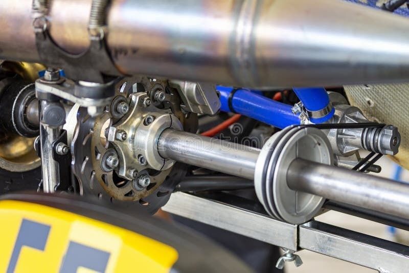
- Positive scrub radius places the tire contact patch outward from the steering-axis intersection.
- Zero scrub radius places the contact patch center directly on the steering-axis intersection.
- Negative scrub radius places the contact patch inward from the steering-axis intersection.
SAI and KPI also influence camber gain, steering effort, wheel-lift behavior, and the jacking effect produced as the wheel turns. Changing ride height, ball-joint position, control-arm angle, or strut-top location can therefore alter more than static camber. A measurement that ignores the complete steering-axis line may produce an alignment that looks correct on paper while leaving the car with poor feedback and excessive sensitivity to road inputs.
Geometry at the Contact Patch: Positive vs. Negative Scrub Radius
OEM chassis engineers generally aim for a modest negative scrub radius, or a value close to zero, because it reduces the torque created when the left and right tires experience different braking or road forces. In a diagonally split braking system, a failure or pressure loss on one circuit can create unequal braking force across the front axle. Negative scrub helps the affected wheel produce a stabilizing response rather than aggressively steering the car toward the side with more braking force. It also helps front-wheel-drive cars resist some steering disturbance during acceleration and improves straight-line behavior when tire grip is uneven.
Zero scrub is not automatically ideal for every vehicle. It can reduce kickback, but the steering may feel vague or unusually light depending on caster, tire construction, steering ratio, and compliance. Positive scrub can be useful in selected rear-wheel-drive or racing applications when the entire chassis is designed around it, including steering assistance, tire stiffness, brake balance, and driver preference. The problem is uncontrolled positive scrub created by wheel fitment rather than deliberate suspension engineering.
| Scrub condition | Typical steering effect | Braking and tire behavior |
|---|---|---|
| Positive | Heavier effort, stronger kickback, greater tramlining | More pull under split braking, increased scrub wear and bearing load |
| Near zero | Low disturbance with potentially reduced self-centering feel | Limited braking reaction, but overall behavior depends on caster and tire design |
| Negative | More stable response to bumps and unequal traction | Reduced brake pull and improved straight-line control in many road-car layouts |
With excessive positive scrub, the contact patch becomes a torque-multiplying lever. A single front tire that hits a bump or finds more grip under braking can generate a moment around the steering axis. That moment travels through the upright and tie rod into the steering rack. On a manual rack, the driver feels it directly. On a power-assisted system, assistance may mask the effort while leaving the car just as sensitive, which can make the problem harder to diagnose.
How Wheel Offsets and Tire Diameters Compound the Problem
Wheel offset, or ET, is the distance between the wheel mounting face and the wheel centerline. Lowering ET moves the wheel centerline outward. A spacer has the same basic effect because it moves the mounting face inward relative to the wheel. As a first-order calculation, reducing offset by 20 mm increases the wheel centerline position by approximately 20 mm. Unless another geometry change moves the steering-axis intersection outward by a similar amount, scrub radius becomes approximately 20 mm more positive. The exact loaded contact-patch change depends on tire shape, rim width, camber, and sidewall deflection, but the direction of the change is predictable.
Tire diameter introduces a less obvious variable. The steering axis is angled, so changing the road contact height changes where that angled line intersects the road. A taller tire raises the loaded contact surface and can shift the intersection laterally; a shorter tire lowers it and shifts the intersection in the opposite direction. The change is often smaller than the effect of a large spacer, but it matters when a setup is already close to the limit. Different tire constructions can also place the actual contact-patch center in a different location than the wheel rim centerline suggests.
- Measure loaded tire width, not only the advertised section width.
- Account for wheel offset, spacer thickness, rim width, and actual backspacing together.
- Recheck scrub radius after changing tire diameter or ride height.
- Inspect caster and camber before blaming the tire for every steering disturbance.
Excessive scrub also magnifies the consequences of bumpsteer and compliance steer. Bumpsteer is suspension-induced toe change as the wheel moves through bump and rebound. If the tie rod and control arm travel through mismatched arcs, a single-wheel bump can alter toe and create a steering correction. The larger the scrub lever, the more torque is generated by the resulting tire force. Hard cornering adds lateral load, tie-rod tension, bushing deflection, and rack movement, so a car can feel acceptable on smooth pavement yet become unpredictable on a bumpy track. The bumpsteer technical guidance emphasizes that the correct solution must be measured on the individual chassis rather than assumed from a universal spacer or correction kit.
Garage-Floor Measurement and Hardware Corrections for Track Stability
A reliable measurement does not require a race shop alignment rack, although the car must be supported safely and loaded consistently. Use a level surface, record ride height at the center of the hub, and place the vehicle at the intended running weight. Check tire pressures, remove obvious play from wheel bearings and steering joints, and use a straightedge or vertical plumb reference to establish the wheel centerline. The goal is to measure the loaded geometry at the ride height where the car actually spends its time, not an unloaded suspension position.
- Measure the wheel mounting face to the wheel centerline, confirming the actual offset and spacer thickness.
- Mark the tire contact patch center on the floor using a plumb line from the hub or wheel center, then verify it against the loaded tread.
- Identify the upper and lower steering-axis pivots, using the strut-top center and ball-joint center on a MacPherson system or both ball joints on a double-wishbone system.
- Project a straight line through those pivots to the floor. A laser, taut string, or carefully positioned angle reference can help, but the reference must remain square to the hub plane.
- Measure the lateral distance between the projected steering-axis intersection and the contact-patch center. Repeat on both sides and record the result at several steering angles if practical.
Camber correction should be chosen with the steering axis in mind. A top-mount camber plate can move the strut top laterally and fore-aft, changing camber and often caster while preserving more of the lower ball-joint relationship. Moving a lower control-arm pivot, changing the ball-joint position, or relocating the rack can have a larger effect on SAI, KPI, and scrub. That does not make lower-arm changes wrong, but it means the resulting steering-axis geometry must be measured rather than inferred from the alignment printout.
For a track build, high-offset wheels with sensible backspacing are usually the cleanest starting point. They preserve more favorable scrub while allowing a wider tire, better brake clearance, and adequate inner suspension clearance. Extended ball joints, corrected spindles, and roll-center correction parts can restore control-arm angles after lowering, but they are not magic scrub-radius fixes. A ball joint that changes roll center may also change steering-axis inclination, bumpsteer, camber gain, and track width. After any hardware change, check toe through bump and rebound, verify brake-line and wheel clearance, and confirm that the tire does not contact the chassis at full lock and compression.
Reclaim Predictable Steering Feedback and High-Speed Grip
Every wheel or ride-height change deserves a front-end geometry audit. Before approving a new fitment, check the following:
- Actual wheel offset and spacer thickness
- Loaded tire centerline and contact-patch width
- Steering-axis intersection at the intended ride height
- Scrub radius on both sides of the car
- SAI or KPI changes caused by ball joints, struts, spindles, and control-arm pivots
- Bumpsteer, tie-rod angle, and bushing deflection under suspension travel
- Brake pull, steering kickback, wheel-bearing load, and tire wear during testing
A wide tire and aggressive stance can support lap times when the suspension, brakes, steering rack, and wheel bearings are engineered around them. The same parts can damage confidence when installed only to create wheel poke. Mechanical grip comes from keeping the contact patch loaded and predictable, while useful steering feedback comes from controlled resistance rather than random impact torque. A car that tracks straight under braking, communicates front-tire load, and absorbs a single-wheel bump without changing direction will usually be faster and easier to place than one that merely fills the fenders.
Prioritize high-speed stability, brake consistency, and repeatable steering feel over extreme offset numbers. Start with the desired tire, calculate wheel position, project the steering axis, and then select correction hardware based on measured geometry. That process preserves the aggressive appearance where it fits, while keeping the front suspension working as a coordinated system instead of turning the contact patch into an uncontrollable torque lever.