Dial Bore Gauge vs. Plastigauge: How to Accurately Measure Bearing Clearances for High-RPM Builds
Dial Bore Gauge vs. Plastigauge for High-RPM Bearing Clearances
The Zero-Tolerance Reality of Competition Bearing Clearances
High-rpm engines do not tolerate educated guesses at the bearing shells. As engine speed, cylinder pressure, oil temperature, and crankshaft loading rise, a clearance error measured in ten-thousandths of an inch can influence oil pressure, bearing temperature, friction, and the survival of the crankshaft. A street engine may provide some margin for an approximate check during routine reassembly, but a serious race, drag, road-race, or high-boost build needs measurements that can be repeated, documented, and verified across every main and rod journal.
The bearing does not protect the crankshaft through simple metal-to-metal contact. Once the engine is running, the rotating journal drags oil into a converging wedge. That hydrodynamic wedge generates pressure and separates the journal from the bearing surface, allowing the assembly to carry massive combustion loads without wiping the overlay or scuffing the crank. The wedge depends on journal speed, oil viscosity, temperature, surface finish, bearing geometry, and vertical oil clearance. King Bearings” clearance guidance makes the key point clear: clearance must be matched to the entire engine system, not selected from a universal number.
Plastigauge still has a legitimate place on the shop floor. It is inexpensive, quick, and useful as a final assembly sanity check when the crankshaft is already installed. However, it is a crushed strip of material compared against a printed scale, not a precision dimensional instrument. For a competition engine where the target may be only a few thousandths of an inch, an outside micrometer and a properly calibrated dial bore gauge provide the control needed to protect the crank and deliver predictable power across the rev range.
How Plastigauge Functions and Where It Falls Short
Plastigauge works by placing a calibrated plastic or wax-like strip across the journal, installing the bearing cap, and tightening the fasteners to the specified torque. The strip flattens as the bearing closes around the journal. After the cap is removed, the compressed width is compared with the supplied scale. A wider flattened strip indicates a smaller clearance, while a narrower strip indicates more clearance.
That process is simple, but the result is highly dependent on technique. The crank must remain completely stationary while the cap is torqued. Turning or shifting the crank can smear the strip and create a misleading reading. Oil, assembly lube, solvent residue, or debris between the journal and bearing can alter the crush pattern. Fastener torque, cap alignment, shell seating, journal condition, and the angle at which the strip is placed also affect the result. The measurement is therefore useful as an indication, but it is not the same as directly measuring the assembled bearing bore.
A static strip check also reports a narrow slice of information. It cannot map the journal or bearing bore at multiple positions, so it will not reliably expose taper, hourglassing, eccentricity, or out-of-round conditions. A journal might show an acceptable strip width at one location while carrying a damaged or undersized area elsewhere. Bearing shells are intentionally eccentric, and the housing can distort when the fasteners are torqued. These details matter because the oil wedge depends on the complete shape of the running clearance, not simply on one flattened strip.
- Crank movement can smear the strip and exaggerate apparent clearance.
- Oil or assembly lubricant can change the crush pattern and reduce confidence in the reading.
- Journal runout, taper, and out-of-round conditions remain hidden unless several points are measured directly.
- The printed comparison scale limits resolution and introduces user interpretation into a small measurement.
- The strip is single-use and cannot establish a documented measurement record for every shell combination.
For builders who need to understand why direct dimensional checks reveal geometry that a crushed strip cannot, an overview of the precision bore gauge principle is useful. A dial bore gauge compares internal dimensions against a known standard, allowing the operator to sweep the bore and identify variation rather than accepting one static impression.
The Dial Bore Gauge Standard for Race Engine Tolerances
The professional workflow begins with an outside micrometer. Each crankshaft journal is measured at several clock positions and locations along its width, using a clean, temperature-stable instrument. Those readings establish the actual journal diameter and reveal taper or out-of-round conditions. The micrometer dimension is then transferred to a calibrated standard, or the dial bore gauge is zeroed directly to the measured journal size, depending on the gauge and shop procedure.
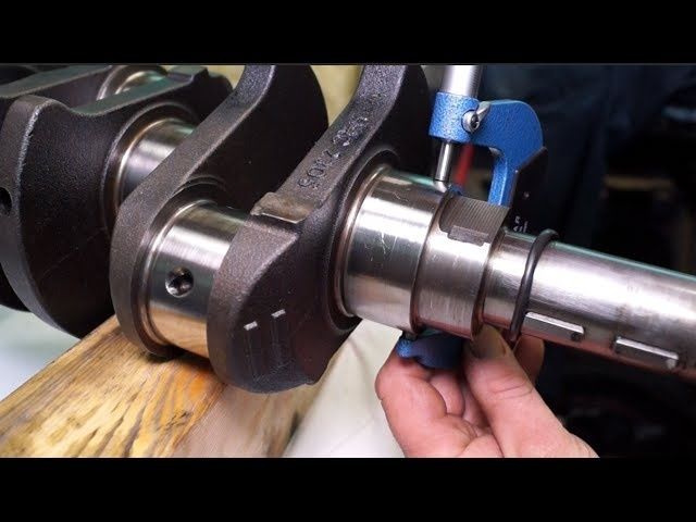
With the bearing shells installed in the block, rod, or main cap and all fasteners tightened to the specified torque, the dial bore gauge measures the assembled bearing ID. The crankshaft is not installed during this step. The difference between the bearing bore and the journal measurement is the actual clearance. This approach separates journal size from housing and bearing geometry, creating a traceable number for each position rather than a rough visual estimate.
- Clean the housing, bearing backs, shells, fasteners, and journals without removing bearing material.
- Torque each cap or rod to the exact specification and sequence required for the assembly.
- Measure every journal at multiple axial positions and clock positions with a quality micrometer.
- Set the dial bore gauge to the verified journal dimension using a standard or the journal itself.
- Sweep the assembled bearing bore to identify the minimum reading and any change through the arc.
- Record vertical clearance, taper, ovality, and shell position before selecting different bearing grades or combinations.
Measurement location is critical. Vertical oil clearance should be taken 90 degrees from the bearing parting line, where the bearing is designed to provide the relevant running geometry. Measurements near the split can be distorted by parting-line relief and crush effects. The MAHLE bearing installation guidance also emphasizes checking eccentricity or ovality away from the parting line, commonly at least 3/8 inch from that area.
A gauge sweep should not be treated as a ceremonial movement of the tool. The operator needs to rock the gauge through the bore until the smallest reading is found, then compare the result at different axial locations. Changes from front to rear can identify taper; changes from side to side can reveal ovality or housing distortion. The desired number is the true vertical clearance at the intended running position, supported by an understanding of how the shell is shaped and how the block will behave at temperature and rpm.
Measurement Tools Compared Across Shop Floor Realities
Plastigauge wins on speed, cost, and accessibility. It can be used during final assembly without removing the crankshaft, making it valuable for confirming that a completed short block has no obvious clearance problem. It is also practical for a stock rebuild where factory components, factory oil, and moderate engine speed provide a wider operating margin. Its limitations are resolution, repeatability, single-point information, and reliance on careful handling.
An outside micrometer and dial bore gauge demand more bench time and a higher level of technique, but they provide direct, repeatable data. They also require calibration, clean contact surfaces, proper standards, and attention to shop temperature. Steel components and precision tools change size with temperature, so a measurement taken with cold parts and a warmed gauge may not agree with one taken after the entire setup stabilizes. Lubricant should not be used as a substitute for cleanliness, and the measurement surfaces must be free of grit and burrs.
| Feature | Plastigauge | Micrometer and dial bore gauge |
|---|---|---|
| Measurement type | Crushed-strip estimate | Direct dimensional comparison |
| Resolution | Limited by printed scale and technique | Typically suitable for precision ten-thousandth measurements when calibrated |
| Geometry inspection | Single compressed area | Multiple clock and axial positions |
| Speed | Fast | Slower, especially when measuring every journal thoroughly |
| Best use | Sanity check during assembly | Setting and documenting race-engine clearances |
| Repeatability | Moderate and operator-dependent | High when tools, temperature, and technique are controlled |
In a serious build, the tools are complementary rather than mutually exclusive. Precision instruments establish the clearance and identify geometry problems before final assembly. Plastigauge can then provide an additional check on a selected bearing location, provided the crank is not rotated and the strip is placed on clean, dry surfaces. A mismatch between the two methods should trigger investigation, not a decision to average the readings.
Translating Thousandths of an Inch into Hydrodynamic Longevity
Clearance is an oil-control decision, not merely a machining number. More clearance generally permits greater oil flow, but excessive clearance can reduce minimum film thickness, increase pressure peaks, lower system oil pressure, and promote vibration or metal contact. Too little clearance can restrict flow, raise bearing temperature, and thin the oil as heat builds. The correct target allows the oil wedge to remain stable while carrying combustion and inertial loads.
Journal diameter, viscosity, operating temperature, and speed all change the result. A common starting point is approximately 0.001 inch of clearance per inch of shaft diameter, while many high-performance applications add about 0.0005 inch as a starting adjustment. These are not universal specifications. A large journal, thick racing oil, hot endurance operation, distorted aluminum housing, or aggressive power level may need a different target than a small journal running a light street oil in a rigid block.
Smaller clearances can reduce oil leakage and help maintain pressure, but only when the crankshaft, housing, alignment, surface finish, and bearing geometry are exceptionally accurate. Excessive tightness can starve the wedge as the engine heats, especially if the oil becomes too thin or the housing changes shape. Excessive looseness can bleed pressure away at high rpm and increase oil temperature through unnecessary flow. The practical target is the least clearance that still maintains a stable film under the engine”s actual load and thermal conditions, a balance also explained in King Bearings” technical clearance recommendations.
- Match clearance to journal diameter, oil viscosity, temperature, rpm, and cylinder pressure.
- Consider block material and housing distortion, particularly in high-output aluminum-block combinations.
- Verify crank surface finish and geometry before changing bearing grades to chase a clearance number.
- Use high-performance bearing designs according to their intended load, speed, eccentricity, and crush characteristics.
- Record every main and rod measurement instead of assuming that all positions are identical.
Bearing selection may involve mixing approved shell sizes or using extra-clearance components, but every combination must be measured again. Manufacturing tolerances can create meaningful differences between positions that are nominally the same. Coated bearings may also require consideration of break-in wear because their running clearance can change slightly after the coating has worn in. The engine”s oil pump, galleries, pressure relief system, and drainback capacity must support the selected clearance; clearance alone cannot rescue an inadequate lubrication system.
Build with Repeatable Precision Before You Turn the Key
Plastigauge remains valuable when its role is kept honest. It is a fast secondary safety check that can catch a gross mistake during final assembly, particularly when access is limited or the crankshaft is already in place. It should not be the primary instrument for sizing bearings in a high-rpm competition engine, where taper, ovality, eccentricity, journal condition, and temperature-controlled measurement all influence oil-film stability.
The reliable process is straightforward but not rushed. Measure the crank journals with a calibrated outside micrometer, torque the bearing housings correctly, zero and sweep a dial bore gauge, and document the vertical clearance at each location. Investigate variation before changing parts, and select oil viscosity and bearing design as part of the same system. That bench time costs far less than a wiped bearing, damaged crankshaft, or lost race weekend.
When the clearances are established by repeatable measurements, the oil wedge has a predictable foundation. The result is controlled oil pressure, better heat management, reduced risk of bearing distress, and power delivery that remains durable from initial startup through sustained high-rpm operation. Precision at the stand becomes reliability under load, which is exactly what a serious performance engine must deliver.